Abstract
Overcurrent protection is the core safety barrier of all low-voltage industrial power distribution systems, and standard-compliant high-current fuses act as the first line of defense against short-circuit and overload faults that damage switchgear, motors and transformers. IEC 60269 415V High Current Fuse follows unified international IEC 60269 standards and adopts bolt-on ceramic construction to deliver stable gG/gL full-range protection for 415V AC industrial circuits. This article focuses on the core concerns of electrical engineers and procurement specialists, covering standardized structural design, full performance parameters, material durability, multi-industry application matching, installation specifications and fault response logic. All analysis avoids financial indicators, and centers on safety compliance, thermal stability, breaking capacity and long-cycle operational reliability to offer systematic reference for low-voltage power system configuration.
Table of Contents (Click Each Hyperlink To Jump To Corresponding Chapter)
- 1. Core Design & Standard Definition Of IEC 60269 High Current Fuse Products
- 2. Complete Standard Technical Specification Parameter Table
- 3. Ceramic Housing & Silver-Plated Terminal Material Advantages
- 4. gG/gL Protection Characteristic & Fault Interruption Performance
- 5. Universal Industrial Application Matching Scenarios
- 6. Installation Guidelines & Daily Operation Maintenance Rules
- 7. Frequently Asked Technical Questions For Electrical Procurement & Engineering
- 8. Customized Technical Matching Support
1. Core Design & Standard Definition Of IEC 60269 High Current Fuse Products
IEC 60269 forms the global unified standard framework for low-voltage high breaking capacity fuses, defining strict rules for rated voltage, current carrying capacity, time-current characteristics, mechanical structure and safety test standards. For industrial 415V three-phase distribution networks, high-current fuse links must satisfy both overload slow-blow and instantaneous short-circuit interruption requirements to protect expensive downstream power equipment.
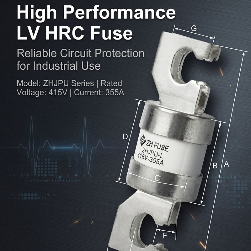
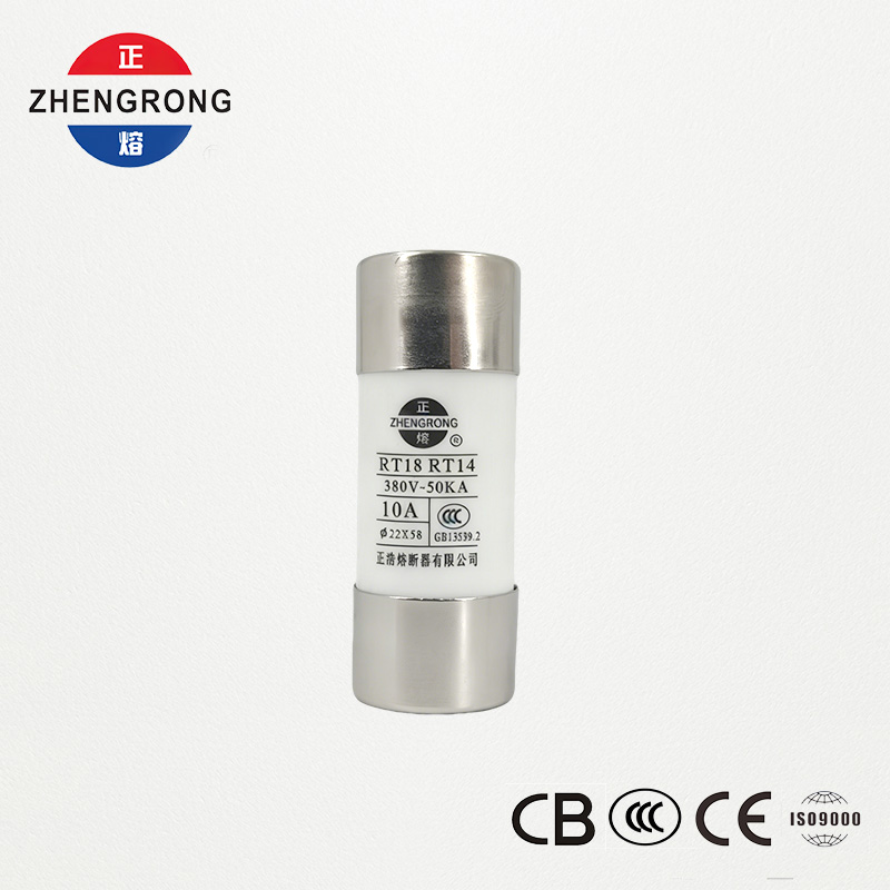
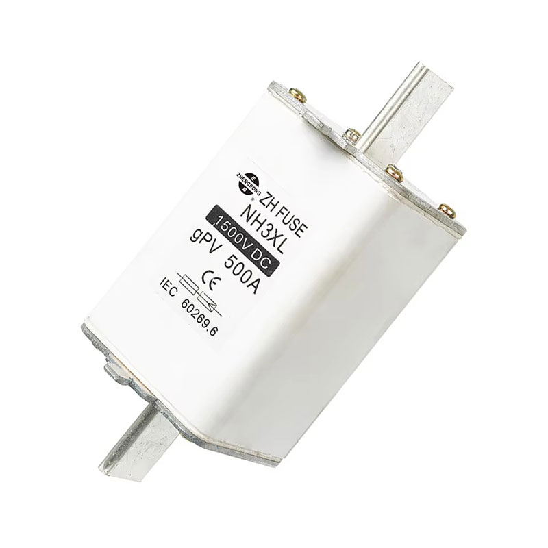
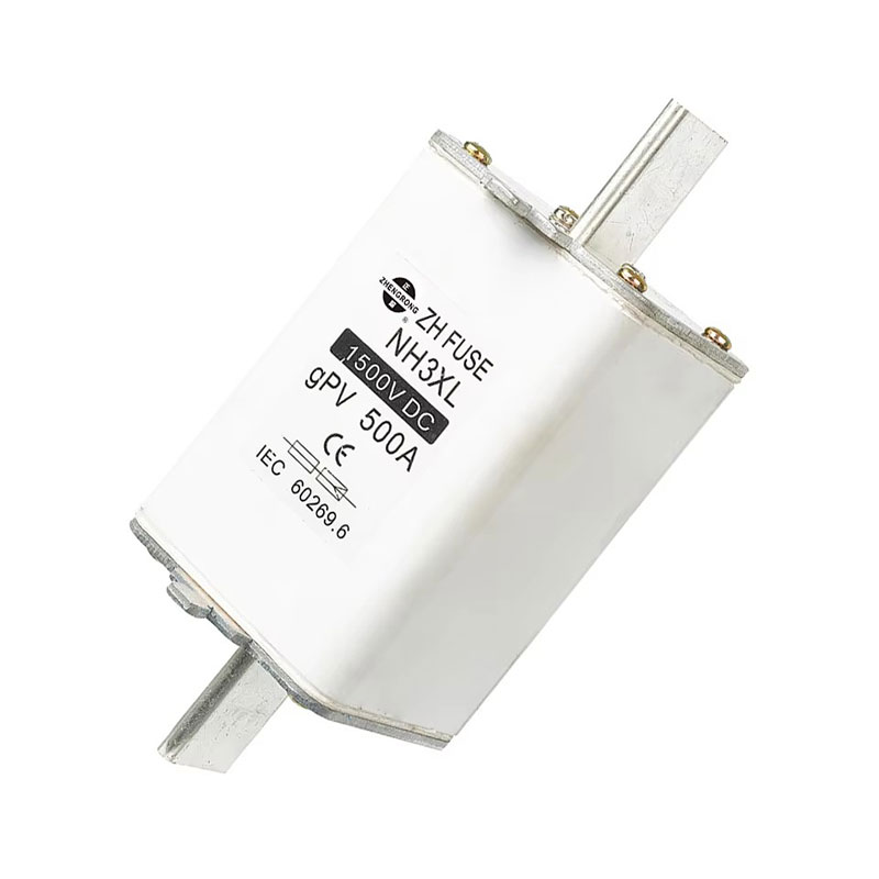
Traditional plastic-shell fuses face obvious defects in high-current industrial environments, including insufficient heat resistance, loose contact terminals and limited breaking capacity. The bolt-on ceramic structure adopted by this product solves these pain points via integrated high-temperature resistant housing and silver-plated copper connecting terminals. As a standardized protection component designed for heavy industrial low-voltage circuits, IEC 60269 415V High Current Fuse unifies dimensional tolerance and electrical performance indicators to achieve cross-project interchangeability for engineering integrators.
1.1 Two Core Functional Design Modules
- Ceramic insulation housing module: High alumina ceramic material blocks arc expansion during fault interruption, with excellent thermal stability to avoid shell deformation under long-term rated current load.
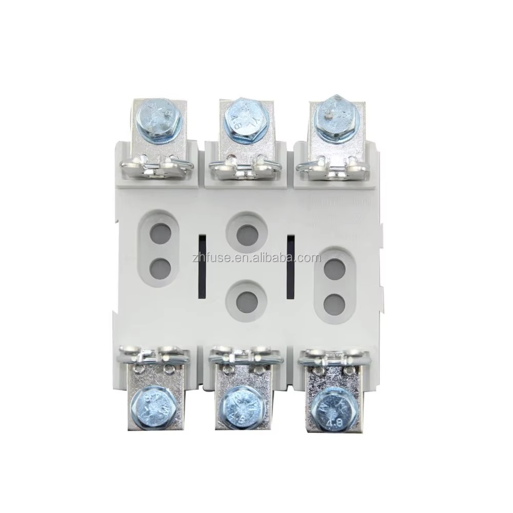
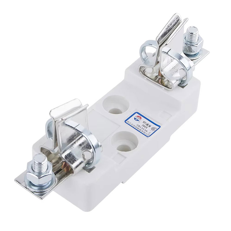
- Bolt-connected conductive terminal module: Silver plating reduces contact resistance between fuse link and busbar, controlling temperature rise at connection points within standard limits even under continuous high-current operation.
- Internal fusible element module: Calibrated metal melt matches gG/gL characteristic curve, achieving graded protection coordination with upstream and downstream circuit protection devices.
1.2 Value Of IEC 60269 Standard Compliance
Products that fully pass IEC 60269 type testing can be deployed in industrial projects across European, Southeast Asian and Australian markets without repeated safety certification. The standard enforces rigorous, short-circuit breaking and mechanical vibration tests to eliminate hidden risks such as arc leakage, shell cracking and premature melting under normal operating current. For procurement teams handling cross-border equipment projects, unified standard compliance greatly simplifies component qualification and project acceptance processes.
2. Complete Standard Technical Specification Parameter Table
Electrical design and procurement rely on clear standardized parameters to complete circuit matching and model selection. This series covers rated current ranges from 200A to 400A under 415V AC working voltage, with unified mechanical and electrical indicators to reduce the workload of repeated parameter comparison during project design. The table below sorts all core fixed specifications applicable to the ZHJPU-L model line.
| Technical Parameter Item | Standard Configuration Value |
|---|---|
| Compliance Standards | IEC 60269, GB13539, CE Certified |
| Rated Operating Voltage | 415V / 500V AC, 50Hz |
| Rated Current Coverage | 200A ~ 400A, typical specification 355A |
| Protection Characteristic | gG / gL Full-range Overload & Short-circuit Protection |
| Housing Construction Material | High-temperature Resistant Ceramic Tube |
| Terminal Material & Surface Treatment | Copper Base With Silver Plating Layer |
| Mounting Mode | Bolt-on Busbar Fixed Connection |
| Breaking Capacity Grade | High Industrial Short-circuit Breaking Capacity |
| Customization Support | ODM / OEM Custom Size & Printing |
2.1 Model Selection Logic For Different Circuit Loads
- Light industrial distribution branches (200A~280A): Suitable for small factory auxiliary equipment, lighting distribution cabinets and low-power control panels with stable uniform load.
- Medium motor control circuits (300A~360A): Matches medium-size three-phase motors, conveyor drive systems and single transformer secondary protection loops.
- Heavy main incoming circuits (380A~400A): Applied to main busbar protection of large power distribution centers, generator output terminals and heavy machinery main power supply loops.
2.2 Unified Shared Design Advantages Across All Current Grades
Every current specification in this product line retains identical ceramic housing structure and bolt terminal layout. This consistent design allows maintenance personnel to use the same installation tools and spare part management standards, avoiding special fixture preparation for different current grades. The unified silver-plated terminal thickness guarantees consistent contact resistance performance across the full product range, eliminating temperature rise deviation caused by inconsistent terminal dimensions during long-term parallel cabinet operation.
3. Ceramic Housing & Silver-Plated Terminal Material Advantages
Material selection directly determines the long-term service life and operational safety of high-current fuses in harsh industrial environments. Low-cost plastic shell fuses use organic polymer materials that soften and deform under sustained high temperature, while bare copper terminals oxidize rapidly in humid or dusty workshops, raising contact resistance and triggering abnormal overheating faults.
The dual material system of ceramic shell and silver-plated copper terminals solves these durability weaknesses simultaneously. High-purity industrial ceramic withstands continuous high temperature without deformation, and the silver plating layer on copper terminals isolates air oxidation to maintain stable conductive performance for years. For industrial power systems running 24 hours daily, this material configuration greatly reduces the frequency of regular component inspection and replacement cycles. IEC 60269 415V High Current Fuse adopts this mature composite material solution to adapt to high-dust, high-humidity and frequent temperature fluctuation factory environments.
- Ceramic housing: High arc suppression performance, prevents arc splashing outward during short-circuit interruption to avoid fire risks inside switchgear cabinets.
- Silver-plated copper terminals: Low contact resistance, minimal temperature rise under full rated load, anti-oxidation and anti-corrosion for coastal or chemical plant workshops.
- Internal filling arc-quenching medium: Absorbs arc energy instantly during fault cutting, supporting high breaking capacity without housing rupture or fragmentation.
3.1 Thermal Stability Performance In Continuous Operation
Under full rated current continuous operation for thousands of hours, the ceramic housing maintains dimensional stability without expansion or cracking. Internal heat generated by the fusible element dissipates evenly through the ceramic wall, avoiding local hot spots that appear on plastic fuse shells. Even in enclosed switchgear cabinets with poor natural ventilation, the overall temperature rise of the fuse link stays within IEC 60269 standard allowable limits, eliminating the risk of adjacent busbar insulation aging caused by excessive local heat accumulation.
4. gG/gL Protection Characteristic & Fault Interruption Performance
gG and gL represent universal full-range protection characteristics defined by IEC 60269, covering two major fault types that threaten industrial power circuits: mild long-time overload and instantaneous severe short-circuit. Many low-grade industrial fuses only support single-type protection, either melting too easily under motor startup surge current or failing to cut off large short-circuit current quickly enough.
4.1 Overload Slow-blow Protection Logic (gL Characteristic)
When circuits face mild overload current between 1.3 times and 5 times rated working current, the fusible element melts gradually with delayed action. This delay avoids false fuse blowing during normal motor startup, capacitor charging and equipment transient current surges, while still cutting power if overload persists for a set time to prevent cable insulation aging and equipment overheating damage.
4.2 Instant Short-circuit Breaking Protection Logic (gG Characteristic)
Once severe short-circuit current occurs from cable shorting, equipment internal breakdown or busbar collision, the internal melt vaporizes instantly to form an open circuit within microseconds. The ceramic shell and arc-quenching filler suppress electric arcs effectively, safely isolating the fault section without arc flash damage to surrounding switchgear components. High breaking capacity ensures the fuse can extinguish extreme fault current without structural rupture or conductive material splashing.
4.3 Selective Coordination With Upstream & Downstream Protection Devices
- Matches miniature circuit breakers, molded case circuit breakers and contactors on downstream equipment to form graded protection coordination.
- Time-current curve design ensures only the fault branch fuse melts during partial circuit faults, avoiding full-system power outage of the entire distribution cabinet.
- Compatible with transformer and generator primary protection coordination requirements for medium and large industrial power supply systems.
5. Universal Industrial Application Matching Scenarios
Standardized 415V three-phase power distribution covers almost all factory, energy and heavy machinery industries globally, and the high-current bolt-on fuse adapts to every core power protection link within these systems. Procurement teams managing multi-industry project portfolios benefit from a single component model that satisfies multiple equipment protection demands, unifying spare part inventory and maintenance training standards across different project sites.
- Industrial power distribution panels & main switchgear: Used as primary overcurrent protection for cabinet incoming busbars, isolating short-circuit faults to protect the whole cabinet wiring structure.
- Motor control centers: Protect three-phase driving motors of conveyors, crushers, pumps and fans from winding burnout caused by locked rotor overload or terminal short-circuit.
- Generator & transformer auxiliary circuits: Installed at output terminals of generator sets and low-voltage sides of distribution transformers to block fault current from spreading to upstream power equipment.
- Heavy-duty machinery & construction equipment: Applied to main power input loops of large cranes, mixing equipment and mining transport machinery operating under variable heavy loads.
- Chemical & environmental protection electrical switchgear: Ceramic insulation structure resists corrosive gas and moisture erosion inside chemical plant control rooms and wastewater treatment equipment cabinets.
6. Installation Guidelines & Daily Operation Maintenance Rules
Correct bolt-on installation and routine maintenance directly extend the service cycle of fuse links and avoid hidden safety hazards caused by improper assembly or neglected inspection. All operation rules follow IEC 60269 auxiliary operation specifications, suitable for on-site electrical maintenance personnel to execute without complex professional training.
6.1 Standard Bolt-on Installation Specifications
- Clean all busbar contact surfaces before installation to remove oxide layers and dust particles that increase contact resistance.
- Tighten mounting bolts with calibrated torque wrenches to avoid loose terminals that generate overheating hot spots.
- Keep vertical and horizontal installation space around each fuse link to ensure natural air convection heat dissipation without blocking by cabinet wiring.
- Align silver-plated terminal surfaces completely with copper busbar planes to avoid point contact and local overheating risks.
6.2 Regular Inspection & Maintenance Standards
During quarterly electrical cabinet inspections, maintenance staff should visually check for discoloration at fuse terminals (a sign of abnormal temperature rise). Any fuse link showing shell discoloration, terminal oxidation or minor deformation must be replaced immediately even without fault melting. After short-circuit fault interruption, the entire fuse link needs full replacement instead of partial repair, as internal melt and arc-quenching filler lose original protection performance once activated.
Storage management requires placing spare fuse links in dry, dust-free warehouse environments to prevent silver-plated terminal oxidation before installation. Long-term stock components should complete visual appearance inspection before delivery to construction sites to filter out products with surface scratch or ceramic shell crack defects.
7. Frequently Asked Technical Questions For Electrical Procurement & Engineering
Q1: Can this fuse series be used in 500V AC circuits besides standard 415V distribution networks?
A1: Yes. The rated voltage upper limit of the product reaches 500V AC, so it can work stably within 415V to 500V industrial three-phase circuits. Users only need to confirm the actual system maximum operating voltage does not exceed 500V before model selection.
Q2: What difference exists between gG and gL protection characteristics for industrial circuit selection?
A2: gL focuses more on long-time overload protection for transformers and distribution lines, while gG strengthens instantaneous short-circuit breaking performance for motor and control equipment. This series integrates dual characteristic performance to support unified application for both circuit types without separate component procurement.
Q3: Is custom dimensional printing and size adjustment supported for special cabinet installation demands?
A3: The manufacturer provides ODM and OEM customization services, including adjusted overall length, surface brand printing and terminal size modification according to customer switchgear cabinet internal layout requirements.
Q4: How to judge whether a fuse link needs replacement after overload operation?
A4: Observe the ceramic shell surface for yellow or black discoloration, check terminal silver plating for oxidation and darkening. Any abnormal surface condition indicates internal thermal aging, requiring full replacement to eliminate potential overcurrent protection failure risks.
Q5: Can multiple fuses of this series be used in parallel to expand total carrying current?
A5: Parallel connection is not recommended. Slight parameter deviation between individual fuse links will lead to uneven current distribution, causing one single fuse to bear excessive load and melt prematurely. Select higher single current grade specifications instead of parallel layout.
Access full technical datasheets and customized low-voltage protection circuit matching plans from Zhejiang Zhenghao Fuse Co., Ltd..