Understand the key electrical ratings, dual-pole isolation design, installation requirements, and application conditions before selecting a DC circuit protection device.
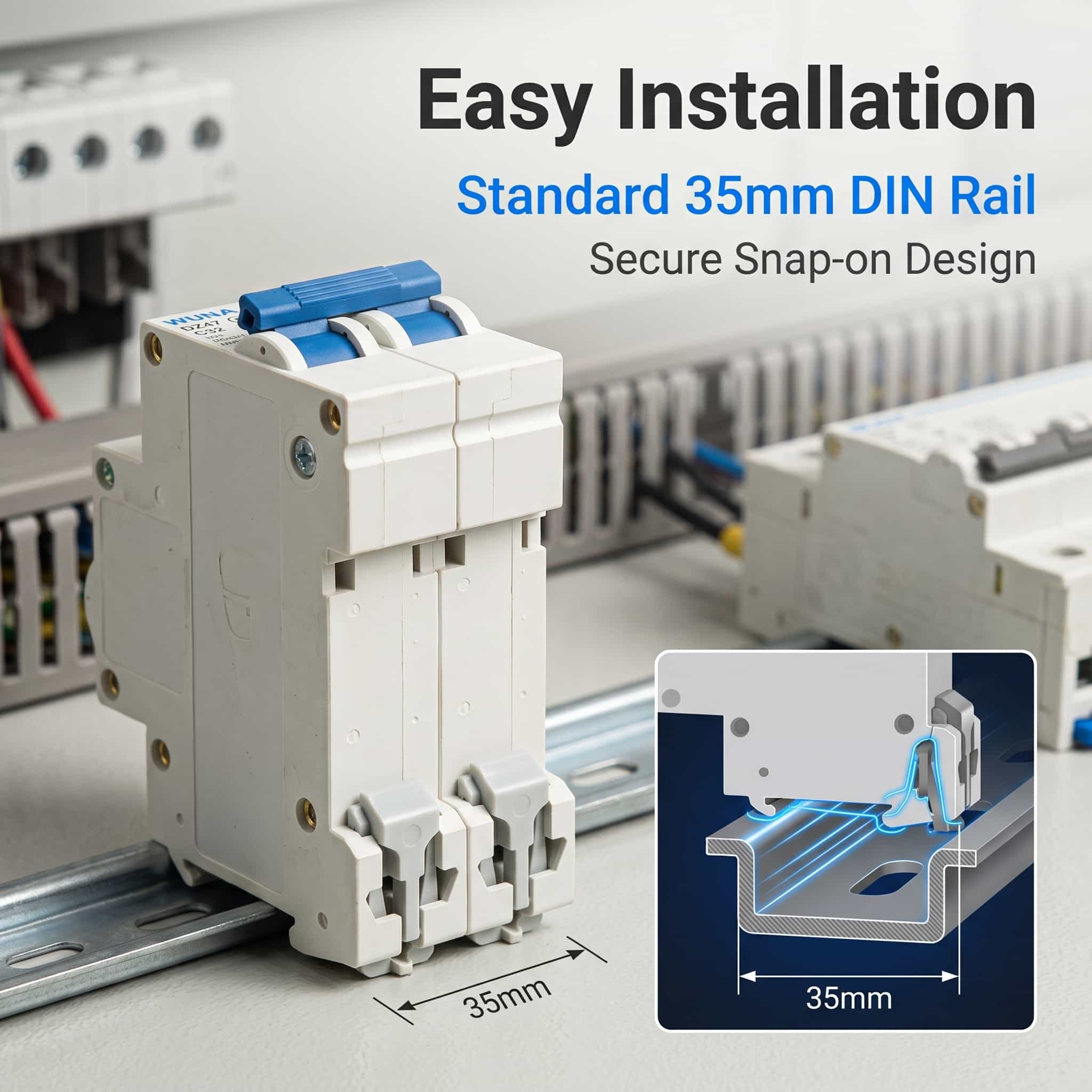
Table of Contents
EXPLORE THE GUIDE1. Understanding the Device and Its Role
A DC miniature circuit breaker is used to switch and isolate a direct-current circuit and, where the product is correctly rated for the application, provide protection against overloads and short circuits. Unlike alternating current, direct current does not naturally pass through zero at regular intervals. Interrupting a DC fault therefore requires a device designed and rated for the relevant DC voltage and current conditions.
The 2 Pole DC Miniature Circuit Breaker DZ47 C32 500V is listed for photovoltaic DC distribution and energy storage applications. The product page describes a compact device that combines circuit switching, isolation, and thermal-magnetic protection. These functions can help simplify the arrangement of protective equipment within a suitable DC distribution enclosure.
Protection and isolation serve different purposes
Overload and short-circuit protection respond to abnormal current conditions within the device's rated operating limits. Isolation, by contrast, provides a means of separating a circuit for inspection or maintenance. A breaker should not be treated as proof that an installation is safe to work on: the system must be shut down and verified according to the applicable electrical safety procedure.
2. Check the Essential Electrical Ratings
Electrical ratings should be reviewed together rather than individually. A device with a suitable nominal current may still be unsuitable if its DC voltage rating, fault-interruption capability, or installation conditions do not match the circuit.
Rated Current
The product designation includes C32, indicating a 32A current rating. Confirm the official nameplate and trip characteristics against the actual circuit load and conductor requirements.
Rated DC Voltage
The product is listed for 500V DC. The maximum possible system voltage, including relevant operating conditions, must remain within the device's specified limits.
Breaking Capacity
The product description lists 6000A. Verify that this value is the applicable DC short-circuit breaking capacity at the intended operating voltage, not simply a general current figure.
Standards and Certification
The product page lists IEC 60898-2 and CE. Check the relevant documentation and certification scope for the intended market and installation.
Technical specifications at a glance
| Item | Product Information |
|---|---|
| Model | DZ47-500V |
| Product Type | DC Miniature Circuit Breaker (DC MCB) |
| Pole Configuration | 2P, for positive and negative DC poles as specified |
| Rated Current | 32A designation; confirm against the official nameplate |
| Rated Voltage | 500V DC |
| Breaking Capacity | 6000A listed; verify the applicable DC rating and test conditions |
| Operating Method | Manual toggle lever |
| Housing Material | Flame-retardant engineering plastic |
| Conductive Components | Copper conductive components |
| Mounting | Standard DIN rail mounting |
| Listed Standards | IEC 60898-2, CE |
3. Why the Two-Pole Configuration Matters
A two-pole DC breaker is designed to switch or disconnect two conductors through a linked mechanism. In a suitable DC circuit, this can support coordinated isolation of the positive and negative conductors. The exact wiring arrangement must follow the manufacturer's terminal markings and the circuit design.
Points to confirm before wiring
- Identify the positive and negative conductors and check the polarity markings.
- Follow the terminal diagram and any specified line/load direction.
- Confirm whether the product permits the proposed wiring arrangement for the intended DC voltage.
- Use conductors and terminal connections appropriate for the circuit current and installation environment.
- Ensure that isolation and protection requirements are met across the complete system, not just at one component.
Correct pole configuration is particularly important when the circuit design requires both conductors to be disconnected. The device's two-pole construction alone does not determine the correct wiring method; polarity, system grounding, and manufacturer instructions must also be considered.
4. Design and Installation Details
Mechanical features affect how a circuit breaker is installed, inspected, and maintained inside a distribution enclosure. The supplied product information describes a front status indicator, a manual toggle lever, a flame-retardant housing, copper conductive components, and a DIN rail mounting structure.
Visible status indication
A front indicator can help maintenance personnel check the device's displayed operating state without dismantling the enclosure. The indicator should be interpreted according to the manufacturer's instructions and should not replace electrical testing when confirming that a circuit is de-energized.
DIN rail mounting
Rail mounting supports organized assembly inside compatible distribution boards and combiner boxes. Before installation, check rail compatibility, enclosure clearance, terminal access, conductor routing, and the required tightening torque. Adequate spacing and ventilation should be maintained according to the equipment instructions and applicable electrical standards.
Housing and conductive components
The product page identifies flame-retardant engineering plastic for the housing and copper conductive components for current transmission. Material descriptions are useful selection details, but the finished installation still depends on correct conductor sizing, secure connections, environmental suitability, and compliance with the system's protection design.
5. Typical DC Applications
DC miniature circuit breakers are used in a range of low-voltage direct-current distribution arrangements. The specific device must be matched to the electrical characteristics of each circuit and should not be selected on application name alone.
Photovoltaic distribution
In suitable photovoltaic installations, DC breakers may be used in distribution equipment or combiner boxes where the voltage, current, fault level, and wiring arrangement fall within the device's ratings. Designers should account for the electrical characteristics of the PV array and any applicable requirements for isolation and overcurrent protection.
Energy storage equipment
Energy storage systems may include battery circuits, DC distribution sections, and connections to power conversion equipment. These circuits can have different prospective fault currents and operating conditions. A breaker should only be applied where its DC ratings and protection characteristics are appropriate for the specific circuit.
Other DC distribution systems
Some low-voltage DC control and distribution circuits also use miniature circuit breakers. Before installation, evaluate the nominal and maximum voltage, normal load current, conductor capacity, fault current, ambient conditions, and required coordination with upstream or downstream protective devices.
6. A Practical Selection Checklist
Use the following checks to organize technical discussions with a supplier or electrical design team before confirming a device for a project.
- Define the system voltage: Record the nominal and maximum DC voltage, including relevant operating conditions.
- Calculate the circuit current: Consider continuous load, expected operating conditions, conductor ratings, and any applicable derating requirements.
- Check fault conditions: Determine the prospective short-circuit current and verify the breaker’s applicable DC breaking capacity.
- Confirm the pole arrangement: Review the grounding method, conductor configuration, polarity, and isolation requirements.
- Review the installation environment: Check enclosure space, DIN rail compatibility, ambient temperature, ventilation, and terminal accessibility.
- Verify technical documents: Request the applicable datasheet, wiring diagram, certification information, and installation instructions.
- Coordinate the protection scheme: Confirm compatibility with cables, connected equipment, and other protective devices in the system.
A complete selection process considers the breaker as part of the wider electrical system. If any rating or wiring detail is unclear, obtain written confirmation from the manufacturer or a qualified electrical engineer before installation.
7. Frequently Asked Questions
1. What does C32 mean in the product name?
C32 generally indicates a 32A rated current with a C-type trip characteristic. Confirm the exact marking and trip curve in the official datasheet before applying the breaker to a circuit.
2. What does the 500V DC rating indicate?
It identifies the specified DC voltage rating. The system's maximum operating voltage must remain within the manufacturer's permitted limits, and the applicable breaking capacity must also be verified at that voltage.
3. Why choose a two-pole DC breaker?
A two-pole design can switch or disconnect two conductors together where the circuit arrangement requires it. Correct polarity, wiring, grounding, and isolation procedures remain essential.
4. Can this type of breaker be used in a solar PV system?
It may be suitable for a PV DC circuit when the system voltage, operating current, prospective fault current, pole arrangement, and installation conditions meet the device's specifications. Application suitability should be confirmed before use.
5. What should be checked before DIN rail installation?
Check rail compatibility, terminal markings, conductor size, tightening torque, enclosure clearance, environmental conditions, and the manufacturer's installation instructions. Installation and verification should be performed by qualified personnel.
6. Which documents should be reviewed before ordering?
Review the technical datasheet, current and voltage ratings, DC breaking capacity, trip characteristics, wiring diagram, applicable certificates, and installation instructions. Clarify any inconsistent or incomplete specification before confirming the model.
Need Technical Details for Your DC Protection Project?
Share your DC voltage, rated current, circuit configuration, and installation requirements to help confirm whether the device matches your application.
Contact Us